Overview
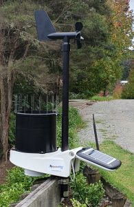
This article will guide you through the complete conversion of the KestrelMet 6000 series weather station. This is relevant for both the Cellular and WiFi models as i’m sure they have the same hardware, but not confirmed. I decided to write this article purely based off the lack of information out there for KestrelMet weather station hardware.
It began when I had the Cellular model, it just kept dropping off the network and every 2 weeks or so and would require a reboot. Also, the latency was a pain and I am within range of WiFi and also a permanent power source, So I decided to pull it apart and have a look inside.
Honestly, I thought this would be a pretty big task, but it actually went pretty smoothly. Most sensors are commonly used sensors such as the temperature, humidity sensors etc, and the rest were pretty easy to figure out. The hardest part was the wind vane directional indicator.
In this article, I will provide details of my setup which does not use the battery or solar charging system as I did not need it, however, implementation would not be hard at all, just an additional sensor or two. At the end of this article, you can find complete wiring diagrams of the ESP and all sensors connected.
Design & Layout
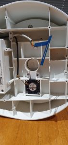
First, lets crack her open and have a look inside.
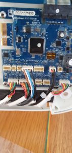
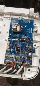
The build quality is pretty nice! All components are coated with a heavy silicon sealant and the quality of the solar panel looks good. Start by removing this hardware and unplug all JST connectors and unscrew the PCB until removed completely. In my case, I also removed the battery and battery board from below the unit as I will supply a permanent power source. If you plan to run this setup using the battery, I suggest you use the deep sleep component.
A small tip, screw the screws back in if you are not using them so they don’t get lost if you ever want to use them again.
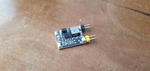
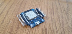
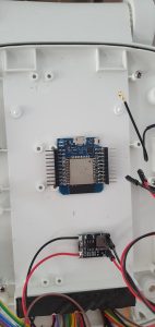
Prepare and mount your ESP32. I used side entry header pins so reinstalling the solar panel would not be an issue later on, or you could just go ahead and solder directly to the ESP if you prefer. Mount the ESP in a way that you can still plug in the USB cable and you have plenty of room for the cables to connect to it, neatly. In my case, I also mounted the 5V regulator here. It does get quite busy towards the end.
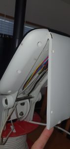
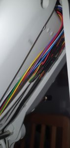
Next, we cut all the cables and remove the JST plugs. I cut them with about 10cm tail in case I needed to re use them. I also made all the cable joins in the lower cable hatch which is on the bottom, directly opposite to the solar panel. This little hatch unscrews with 4 small screws then hinges open. Extend the cables so they are long enough to reach your ESP. Try and remember which cable is which or re label them, if you get mixed up its easy to trace them.
Another note here, try and get them all coming in straight and not over-lapping, as there is a foam pad which presses down on them to create a seal. Not the best pictures but you get the idea.
Temp, Humidity and Pressure Sensors
Now, we will start by connecting the first lot of sensors. These are easy as they are all I2C sensors located at the bottom of the weather station by the fan. If you look carefully, you can see a PCB and another JST connector.
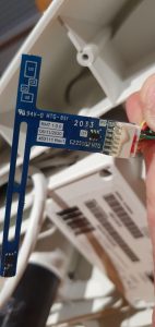
From the cable labelled RHT, the yellow and orange is what you want. The orange is SCL and the yellow is SDA. Enable I2C on your ESP32 and scan the I2C bus.
i2c:
  sda: 21
  scl: 22
  scan: True
In my case, I have used GPIO21 and GPIO22 for my I2C bus. Now, open the esphome log output window and check what devices are found on the I2C bus. You should see the following.
[16:14:09][I][i2c.arduino:069]: Results from i2c bus scan:
[16:14:09][I][i2c.arduino:075]: Found i2c device at address 0x40
[16:14:09][I][i2c.arduino:075]: Found i2c device at address 0x44
Now, some handy resources are the esphome official website and this directory of I2C devices, based on their addresses. Here, we can do a search for what devices are based on what address you received. In our case we can see that we have addresses 0x40 and 0x44. Below are all devices that are possible matches for the I2C address 0x44. I tried each one until I was able to get data from the device.
- INA219 – 26V Bi-Directional High-Side Current/Power/Voltage Monitor
- INA260 – Precision Digital Current and Power Monitor With Low-Drift, Precision Integrated Shunt
- ISL29125 – Digital Red, Green and Blue Color Light Sensor with IR Blocking Filter
- LM25066 – PMBus power management IC
- PCA9685 – 16-channel PWM driver default address
- PCF8574 – Remote 8-Bit I/O Expander
- SHT31 – Humidity/Temp sensor
- STMPE610 – Resistive Touch controller
- STMPE811 – Resistive touchscreen controller
- TDA4670 – Picture signal improvement circuit
- TDA4671 – Picture signal improvement circuit
- TDA4672 – Picture signal improvement (PSI) circuit
- TDA4680 – Video processor
- TDA4687 – Video processor
- TDA4688 – Video processor
- TDA4780 – Video control with gamma control
- TDA8442 – Interface for colour decoder
- TMP006 – Infrared Thermopile Sensor in Chip-Scale Package
- TMP007 – IR Temperature sensor
In our case, and at the time of writing this article, the device we want is the SHT31 – Humidity/Temp sensor. Again, searching the esphome database we can see there is a integration for SHT devices.
sensor:
- platform: sht3xd
temperature:
name: "Weather Station Temperature"
humidity:
name: "Weather Station Humidity"
address: 0x44
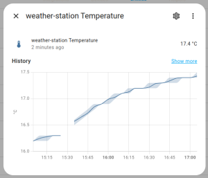
update_interval: 60sSo, add the code to your YAML and go ahead and check the device entities to see if you now have the 2 newly added entities available and outputting the correct data. You can tweak the values as you like such as the update interval. And just like that, that takes care of the Temperature and Humidity sensors. Now, again, at the time of writing this, I was never able to find an exact match, or any compatibility for the devices reported under address 0x40. My guess is this is the Pressure sensor, so this will go on to be the ONLY sensor I could not get working. I will create a feature request to add it to esphome when I identify what it is, and update the article if I ever get it working.
That brings us to the next section, the rain sensor.


