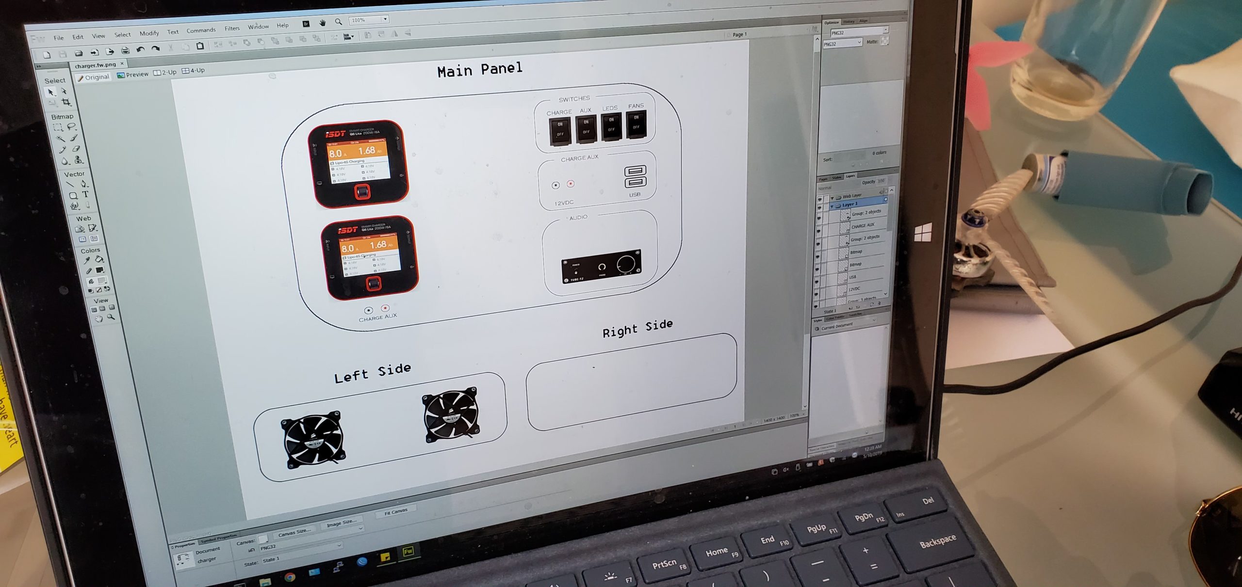
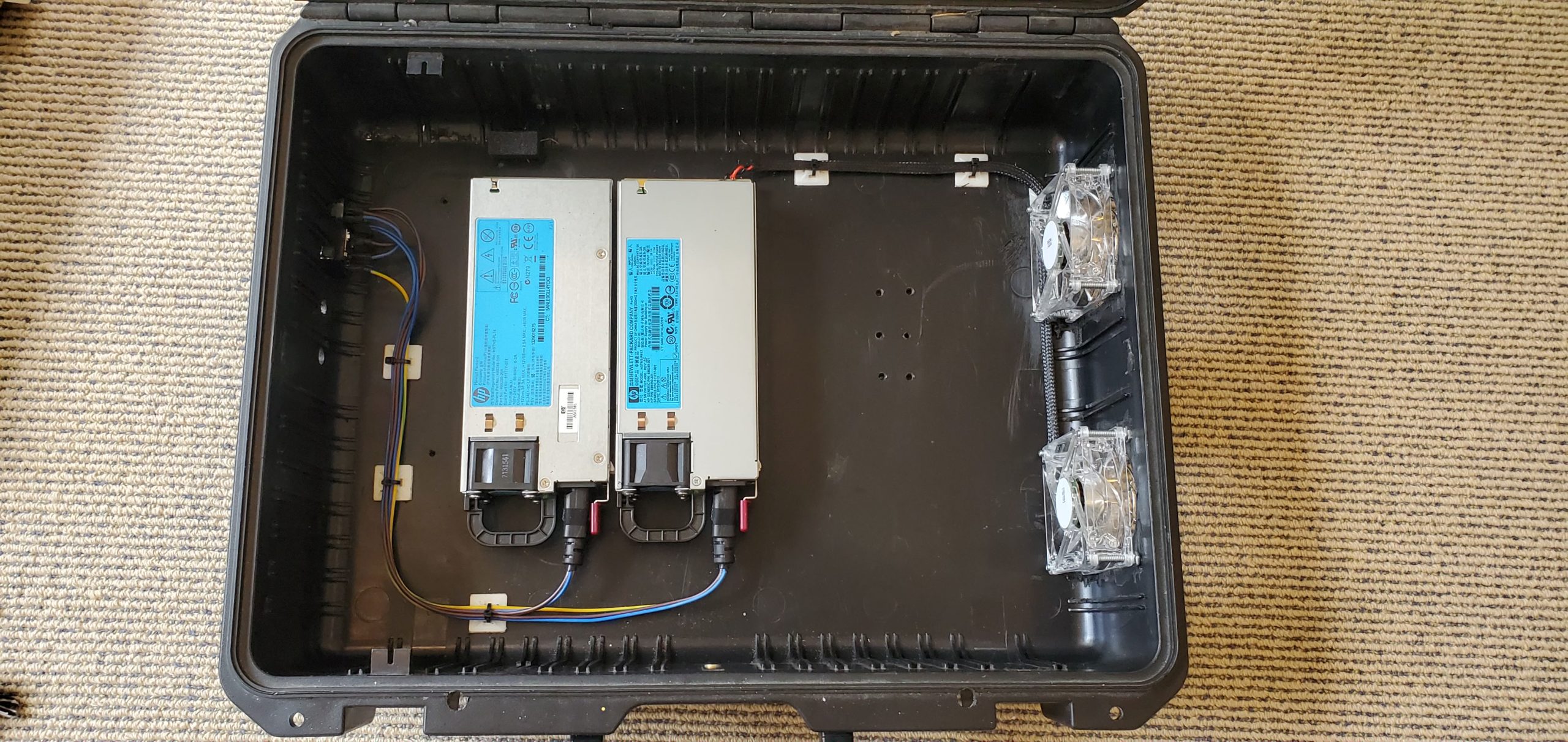
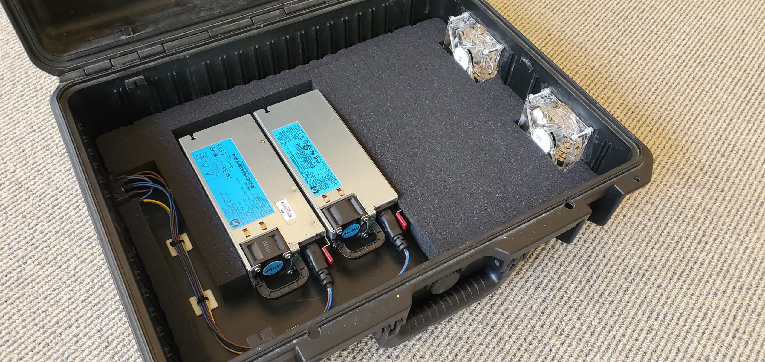
This project is a field charger setup working off both AC or DC for charging. This will be rocking two 40A server power supplies and drive 2 individual chargers for parallel charging multiple packs. Each charger is supplied a individual 40A supply and also rocks build in audio with Bluetooth for you important in field music!
The charger will have both AC and DC inputs on the left side. AC inputs will drive the power supplies and the DC input will bypass the power supplies, leaving the power supply DC rail floating with a throw over switch to select between AC or DC charging.
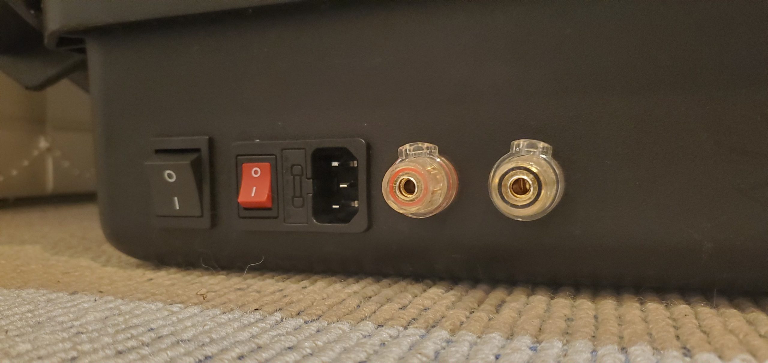
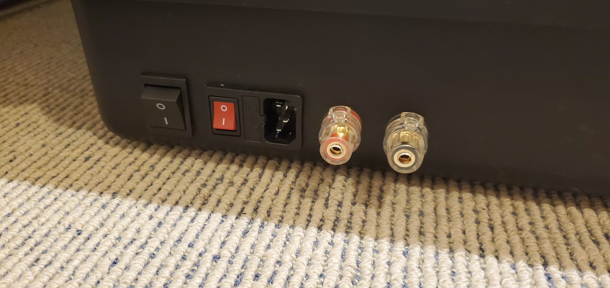
First, I started with installing the IEC plug, DC sockets and the AC/DC throw over switch. Both power supplies will be wired in parallel on the AC side of the IEC socket.
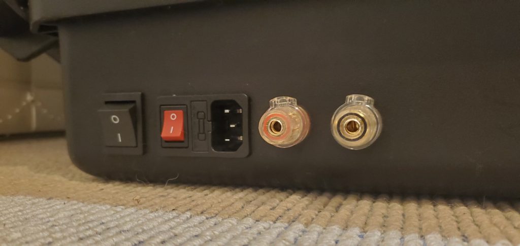
AC / DC inputs and AC / DC throw over switch. 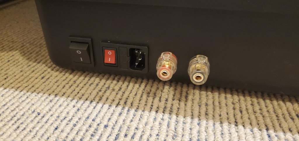
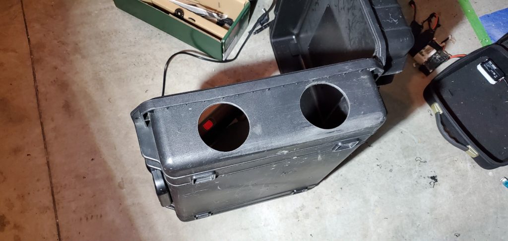
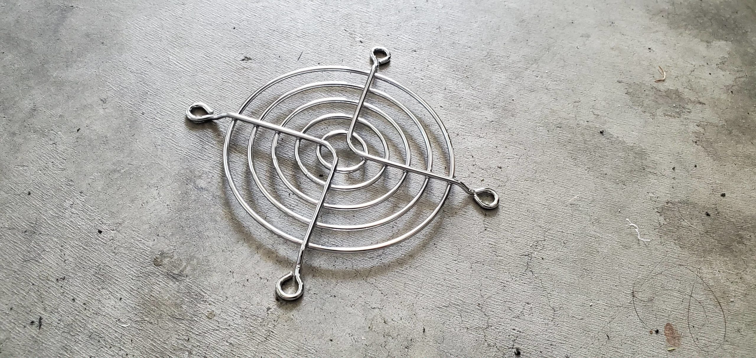
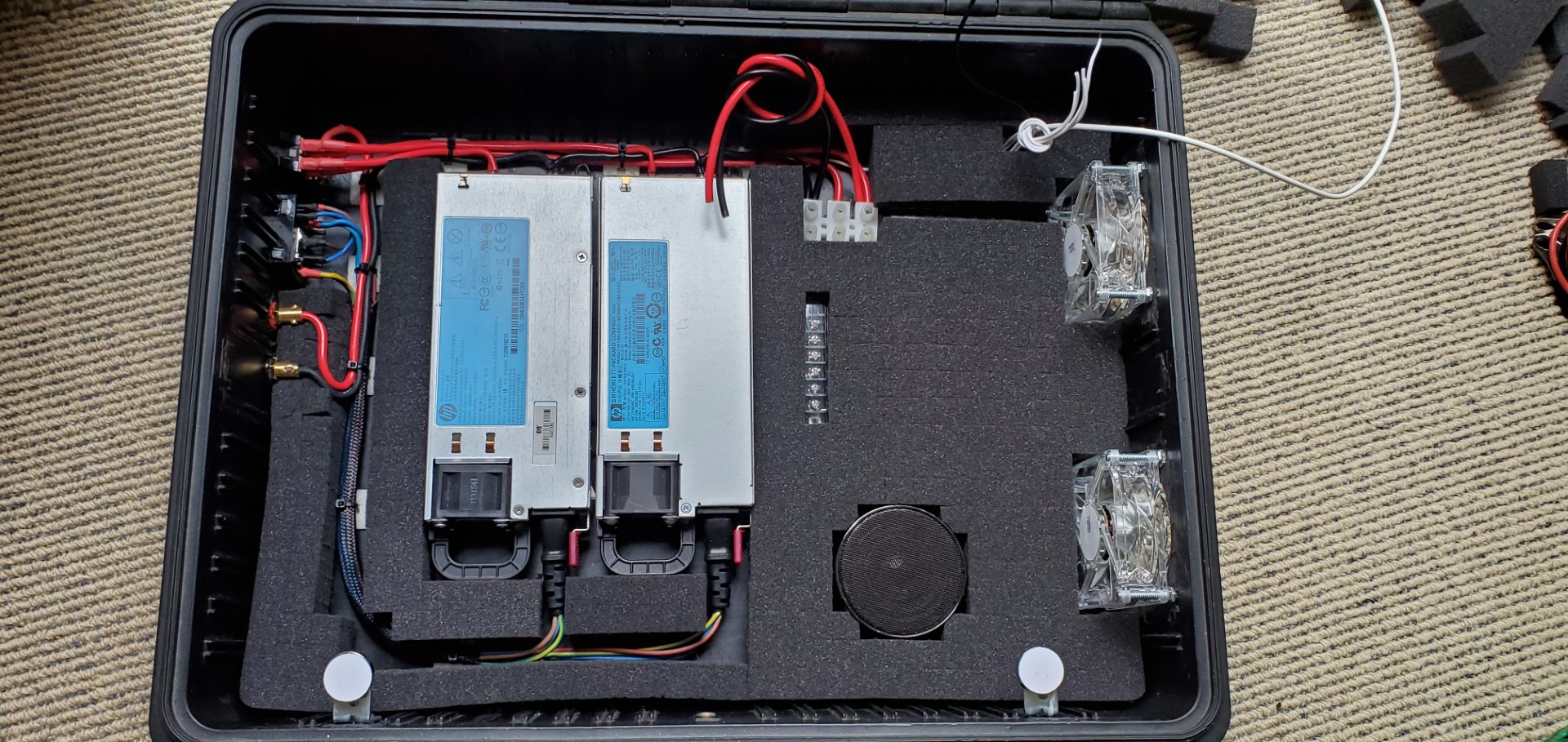
Next, I installed the fans. Two Deep Cool LED illuminated fans are installed into the side of the Pelican Case, and then fan grids are installed over the intakes. The fans will allow ample cooling for the power supplies and chargers, and the blue LEDs will give it a clean finish when the clear perspex switch panel is installed. There will be a dedicated switch on the switch panel for powering the fans.
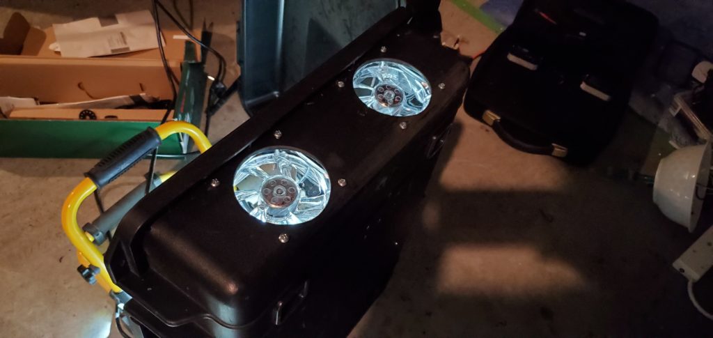
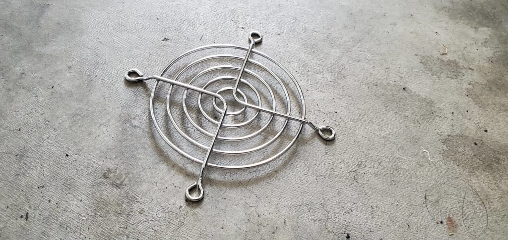
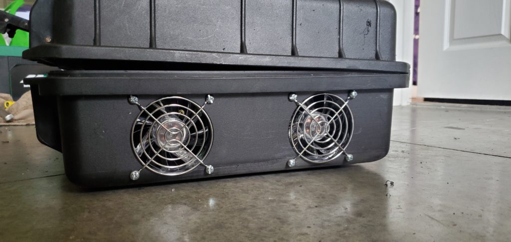
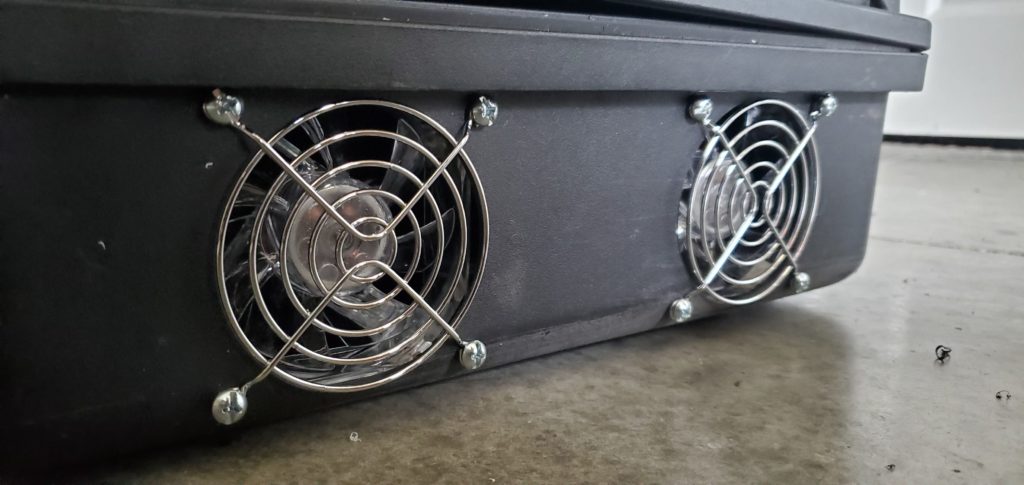
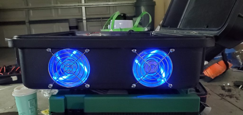
2x Deep Cool 80mm LED fans with grille.
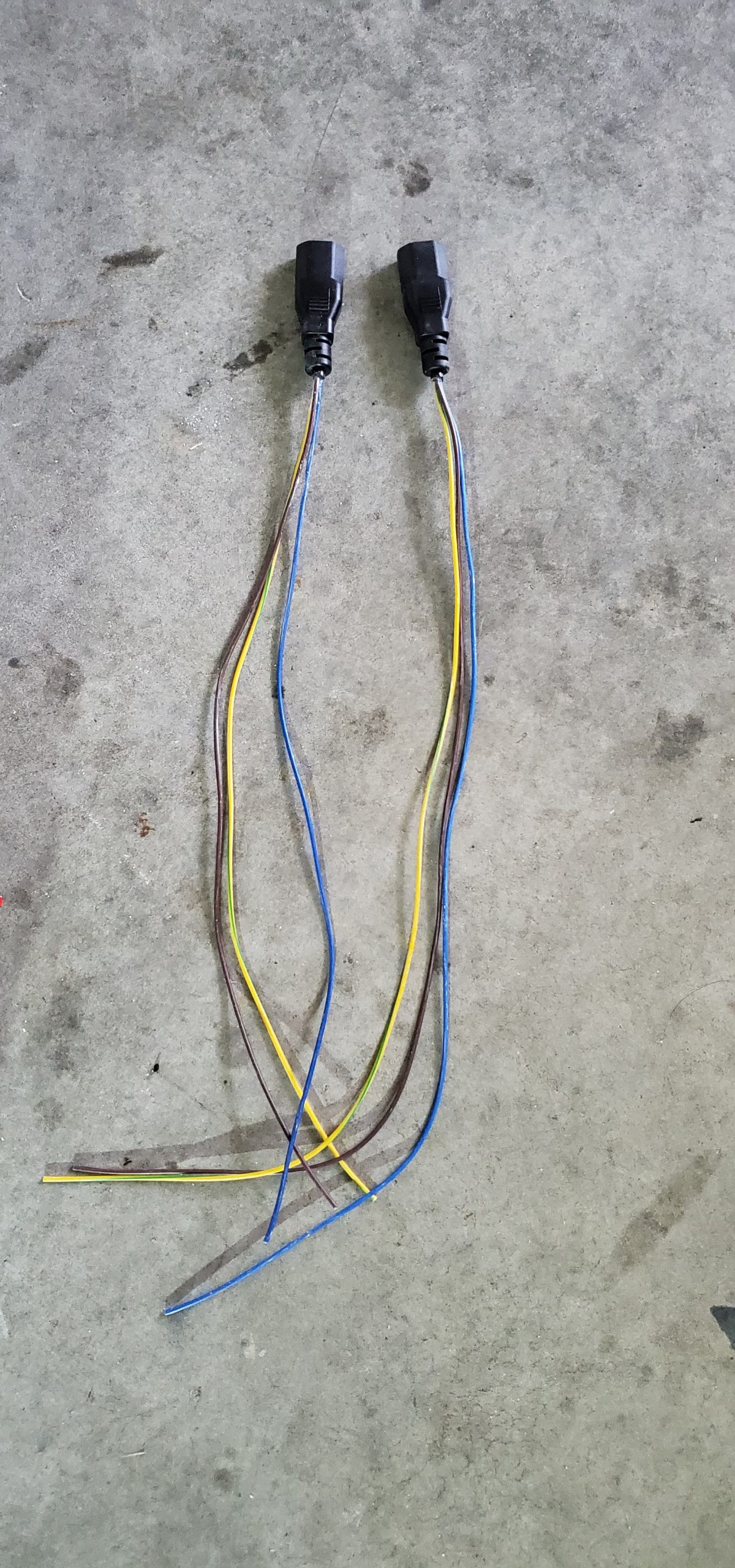
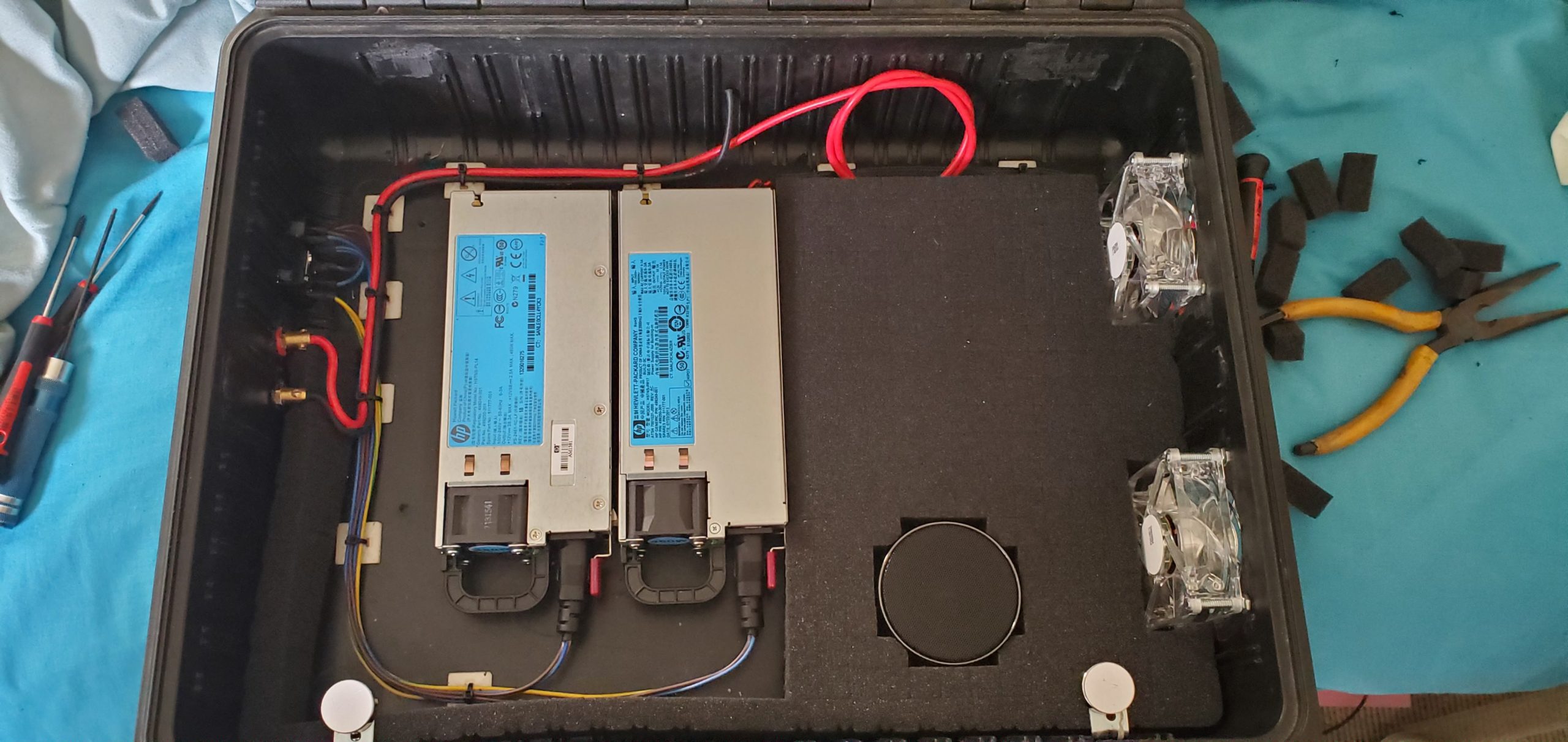
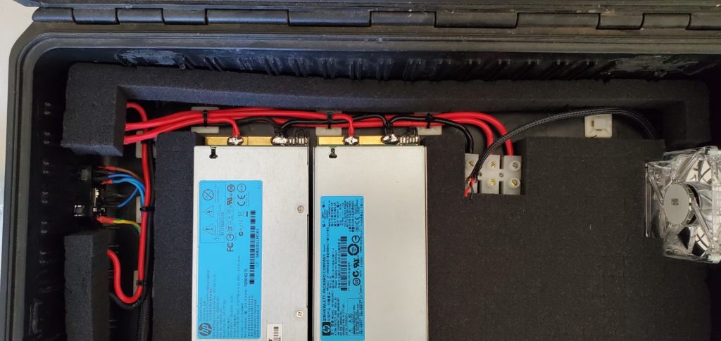
Now, i start mounting and wiring the power supplies. Two jug leads wired directly into the power supply. I have stripped the leads back for easier and neater cable management. When switching between the DC and AC charging circuits, I will always be switching the DC side only, so there is no AC switching other then on the IEC socket itself on the left side of the case which is also fused.
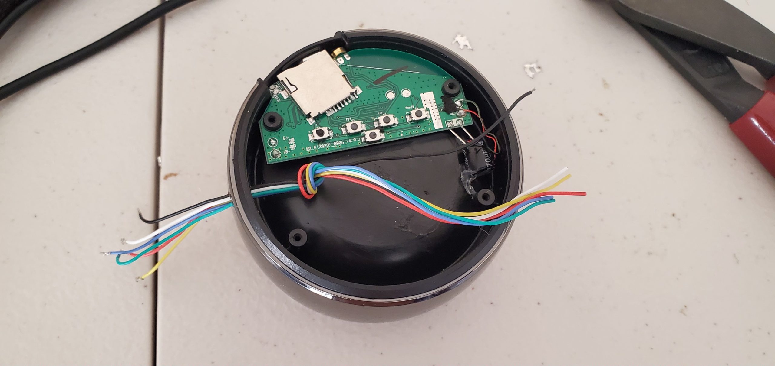
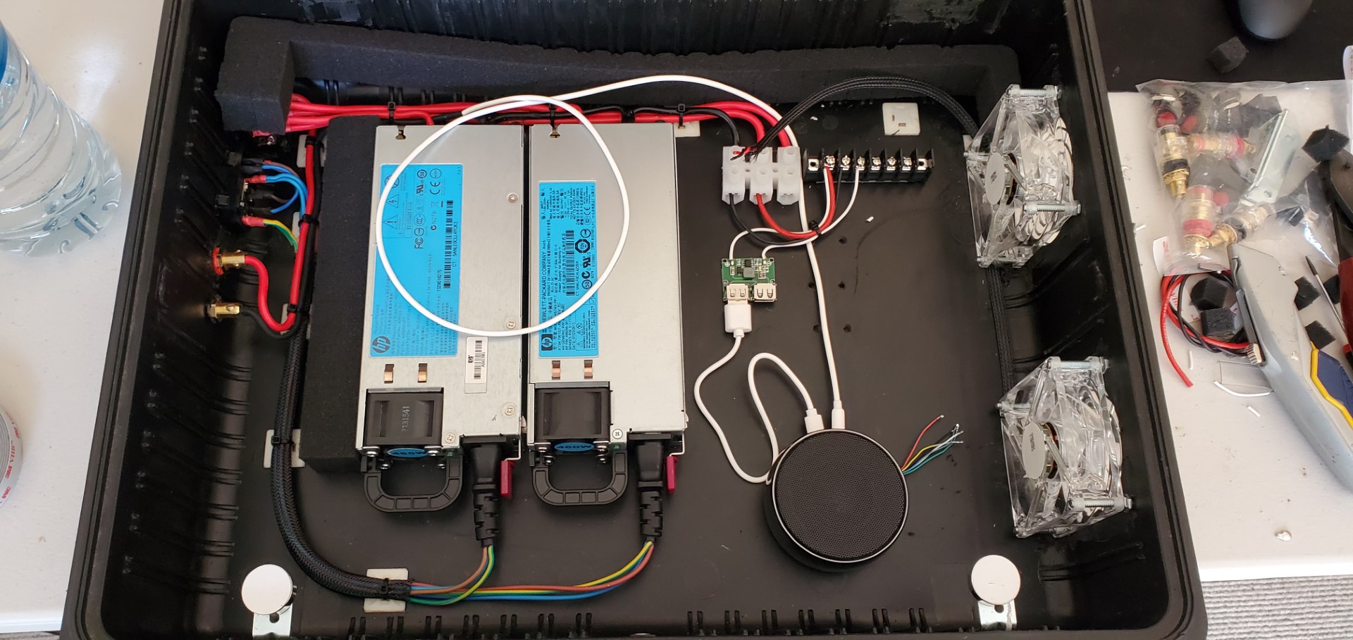
Now, I start to prep the wireless speaker. This is a wireless Bluetooth speaker i bought for about $40NZD, with an awesome sound and good volume levels, I decided to build it into the charger and have both Bluetooth and 3.5mm AUX input options for connecting your phone. All the controls for the speaker will also be wired to the front switch panel, allowing for volume adjustment powering on and off and volume control. I wired directly onto the back of the switches and will extend the cabled to reach the front switch panel with a group of momentary push buttons for control.
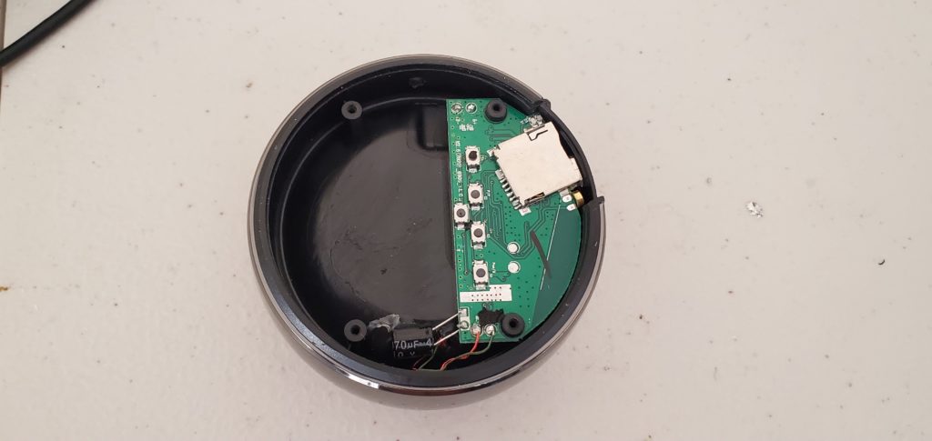

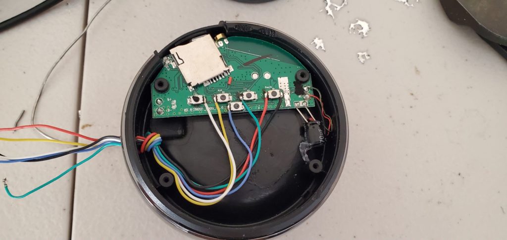
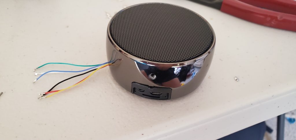
Wires will be extended to the main switch panel for volume and power control. 


Next, we will start with the main charging circuits wiring and switching circuits. There is a double pole double throw rocker switch on the left side by the AC and DC inputs that will switch between AC and DC charging. This will switch the DC side of the circuit only. This means that if the switch is in the DC charging position and AC is applied, the power supplies will still power up but the DC circuit will be floating. When the switch is selected for AC charging, the power supply DC circuit is completed and the DC battery supplied circuit become floating.
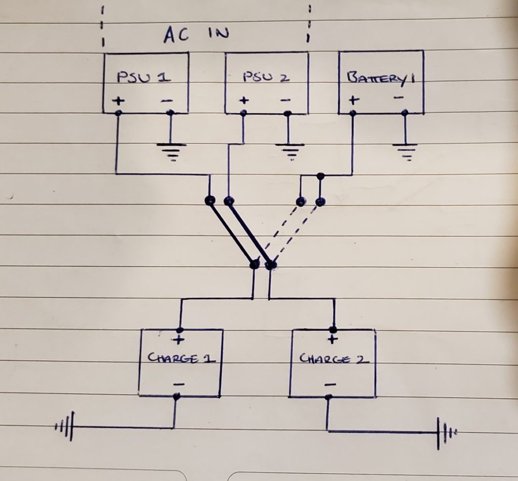
AC and DC switching circuit using a DPDT switch
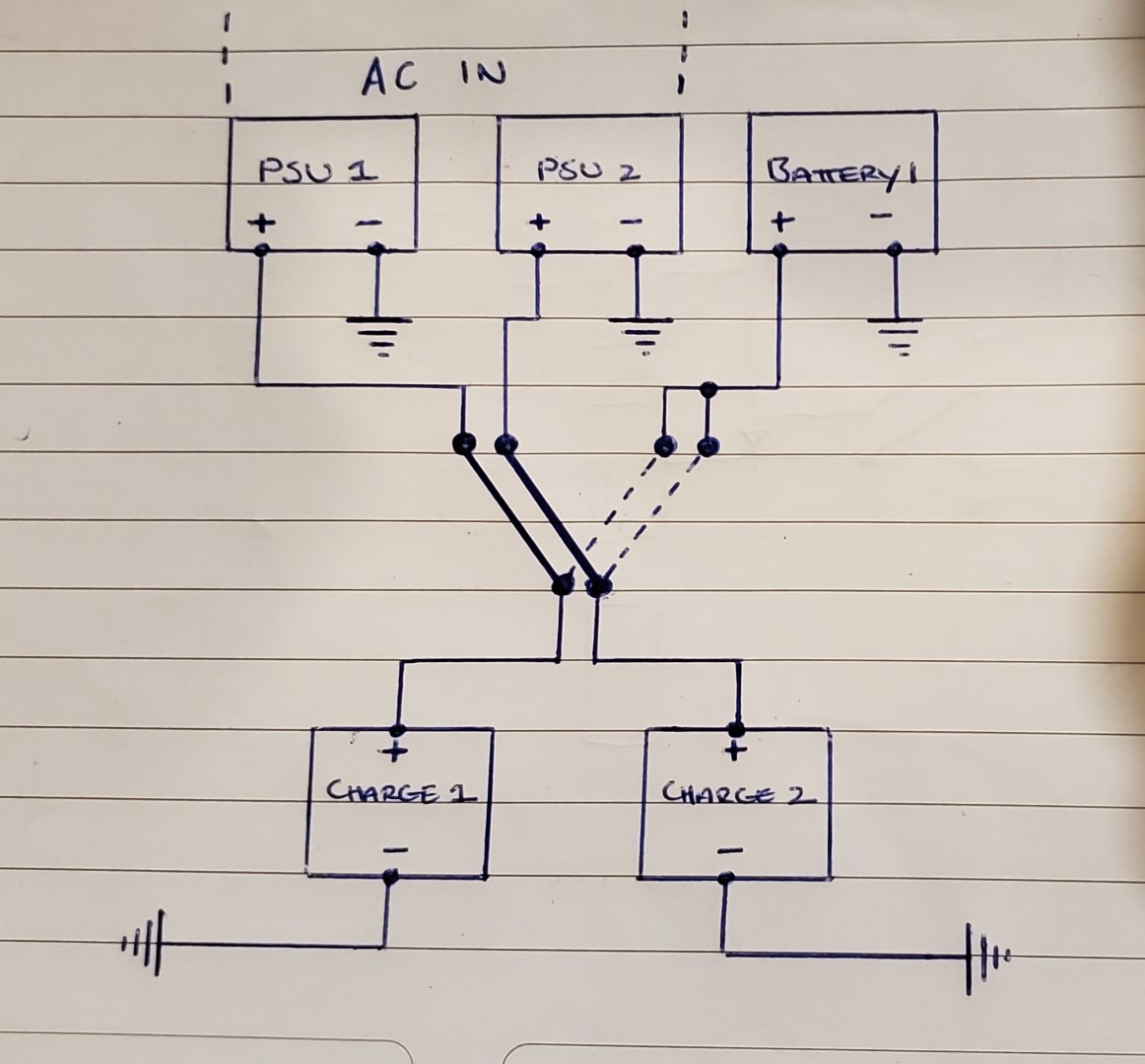
Each power supply provides a individual supply to each charger. They are not in series or parallel, this gives each charger a true 40 amp supply current. Any other devices are powered of either of the two power supplies as current draw is minimal.
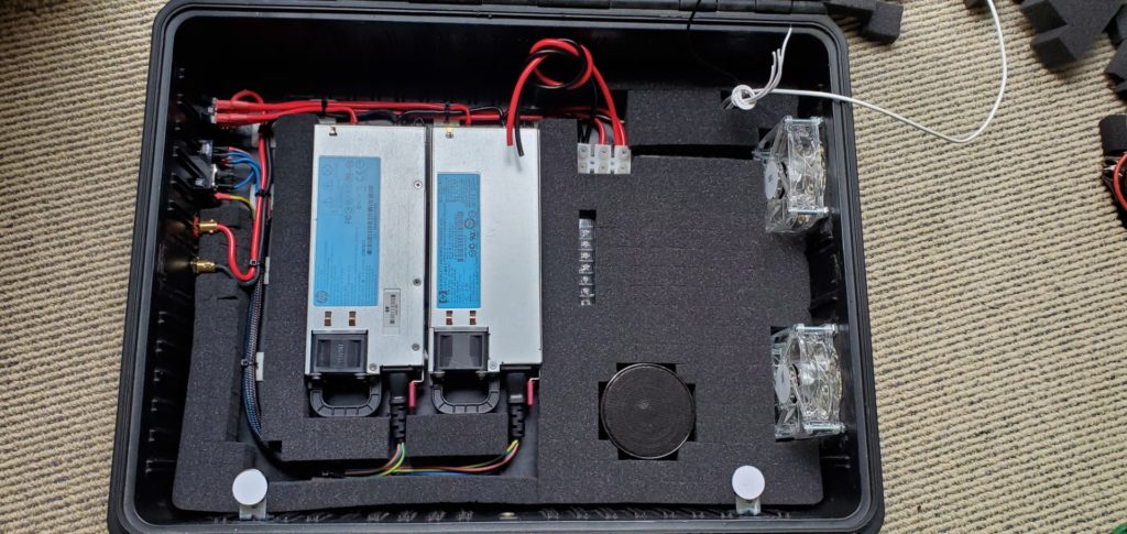
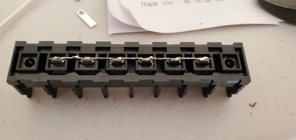
AUX 12v DC output rail 
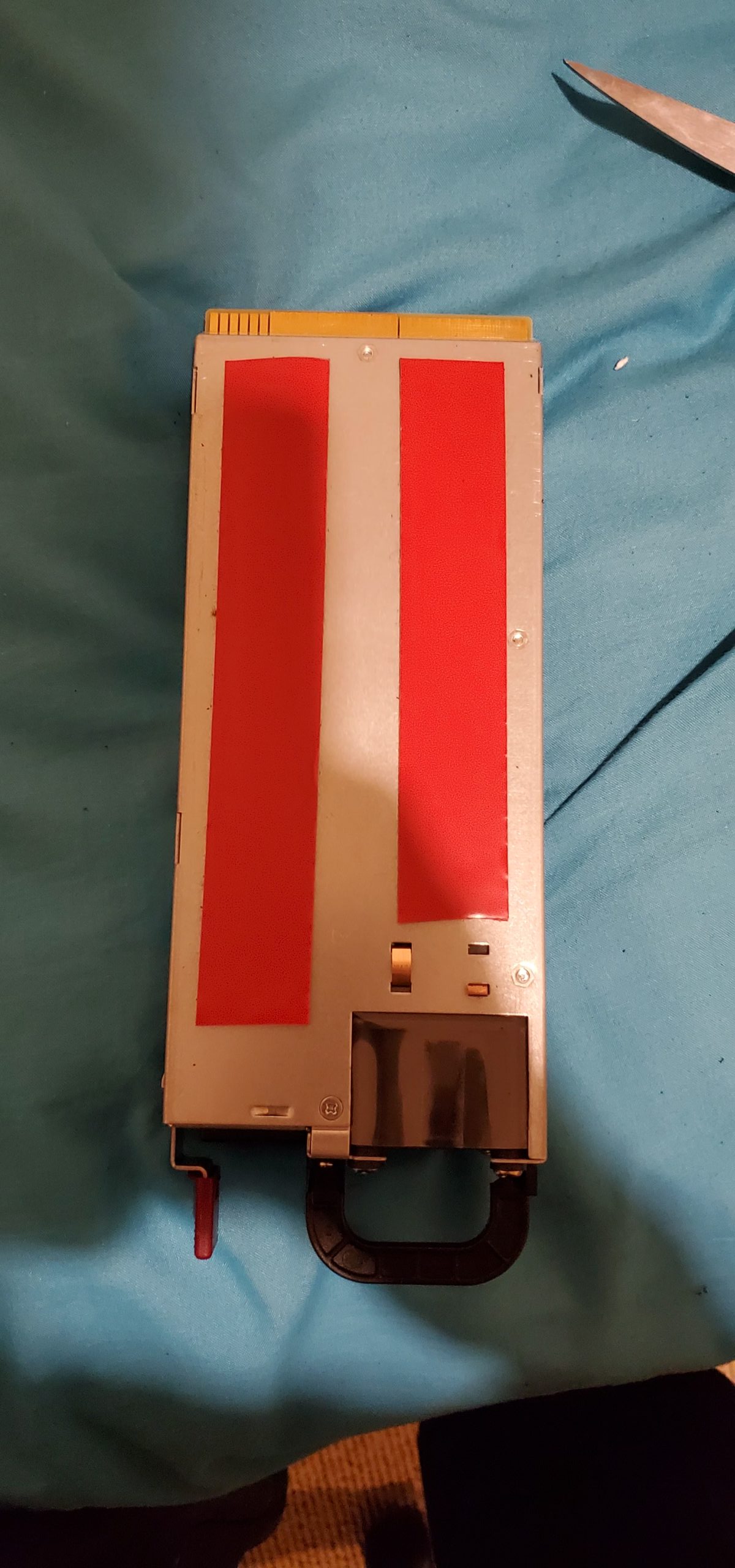
PINS 33 and 36 are jumpered to boot the power supply.


To be continued.


