The RotorHazard project is a fork of the Delta 5 project by Scott Chin, with a vast number of improvements. These improvements include the following.
- Advanced Sensor Tuning with Visual Support
- Improved Web GUI with Responsive Support
- Full LiveTime Integration
- Pilot Heats and Classes
- LED and Audio Integration
- Event, Class, Heats and Rounds
- Missed Lap Recovery using logged RSSI data
- Advanced RSSI Filtering
- JSON API
This project helps record laps when racing FPV, it records lap times and reads them out. The software is opensource and available on GitHub based on the original delta5 project by scottchin.
In this example, I will be using the RotorHazard fork of this project. It provides a very nice web based GUI and good responsive layout on mobile devices.
Each pilot is given a video frequency to transmit on, Say channel F4 (5800 is the frequency for F4). A single node which consists of one RX5808 video receiver and one Arduino nano is then also programmed to listen for activity on F4 5800 and measures the RSSI as pilots pass by the race timer. The timer is calibrated each time the first lap is completed so it knows at which point the RSSI peaks, thus meaning the strongest signal is received from that quad on F4, this is how the timer knows that the quad has passed through the gate where the lap timer is positioned making it accurate and also preventing random lap times being accidentally recorded.
The entire project is python based and runs perfectly on the PI with a web interface for configuring and viewing pilot lap times. I have configured a WiFi AP on the PI with a DHCP server so pilots can connect in field to the timer and view race data. Towards the end of this article is a ready to flash image file with the server up and running, including the wireless access point and information for the image.
Part 1 – Hardware Setup
Here you can watch a full installation and setup video.
Firstly get all the required hardware ready for assembly. A full parts list can be found below. Some extra hardware for a cleaner installation include female pin headers for easily installing and removing and replacing any faulty hardware further down the line should this be necessary, but are not required.
Please, if you find any issues with this article or errors please comment on the post or contact me and I will fix them. Keeping up to date and documenting everything with a project this size and active is quite a task! Your feedback is always appreciated!
Download the latest Pre-Built RotorHazard 2.3.2 Stable Ready-to-Flash Image – See this section for flashing instructions.
Hardware required, with links for purchase.
| PCB | 1 or 2 Delta5 PCB – Each board supports 4 nodes |
| Receivers | 4x or 8x RX5805 RX Modules |
| 5v Regulator | Pololu 5v 2.5A Step-Down Regulator |
| 3v Regulator | Pololu 3.3v 2.5A Step-Down Regulator |
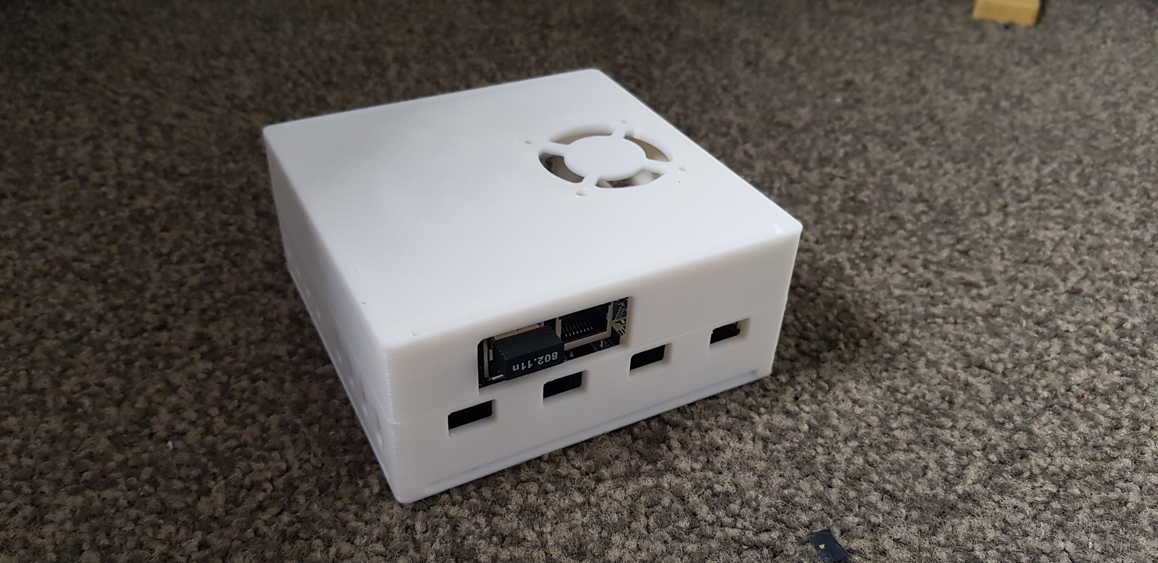
| Case | D5RT 3D Printed Case |
| Fan | 12v 40x40mm DC Fan |
| Raspberry PI | Raspberry PI 4 Model B |
| Arduino | 4x or 8x Arduino Nano |
| Misc | Double Male Header Pins with Jumpers |
| Misc | Arduino Stackable Female Header Pins |
Choose a case. I went with a 4 and 8 node alternative from thingiverse. This is a great looking case and has plenty of room for mounting additional components. There are plenty of options available on thingiverse.
Delta 5 PCD 4 Node Case
https://www.thingiverse.com/thing:2887824
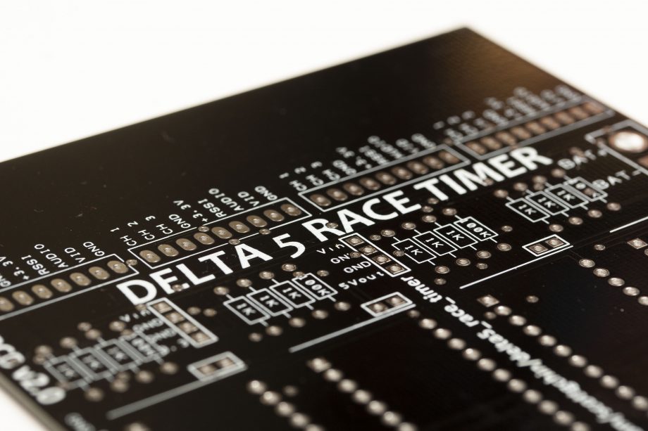
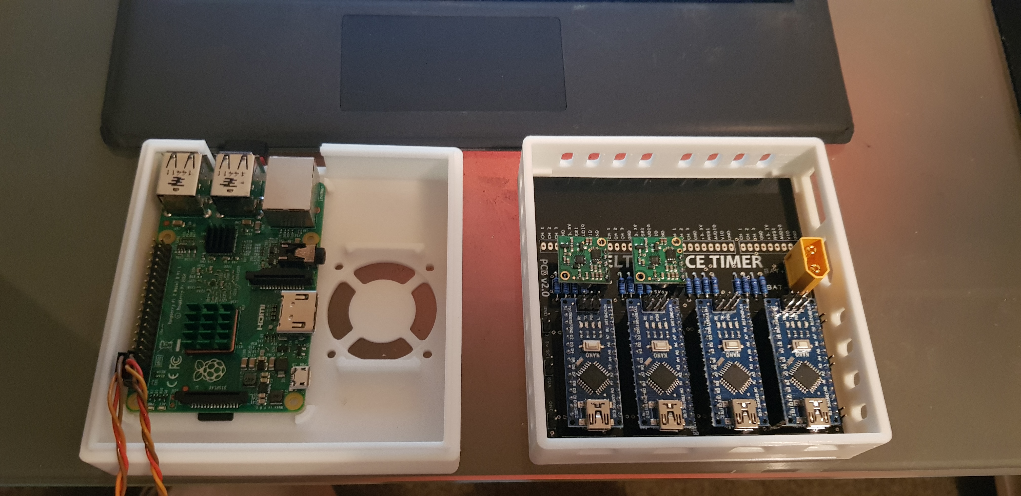
Now lets start with installing the hardware. Lets start with the delta 5 PCB. The board is labelled with each components location so its pretty hard to get things wrong. Lets take a look at the delta5 PCB
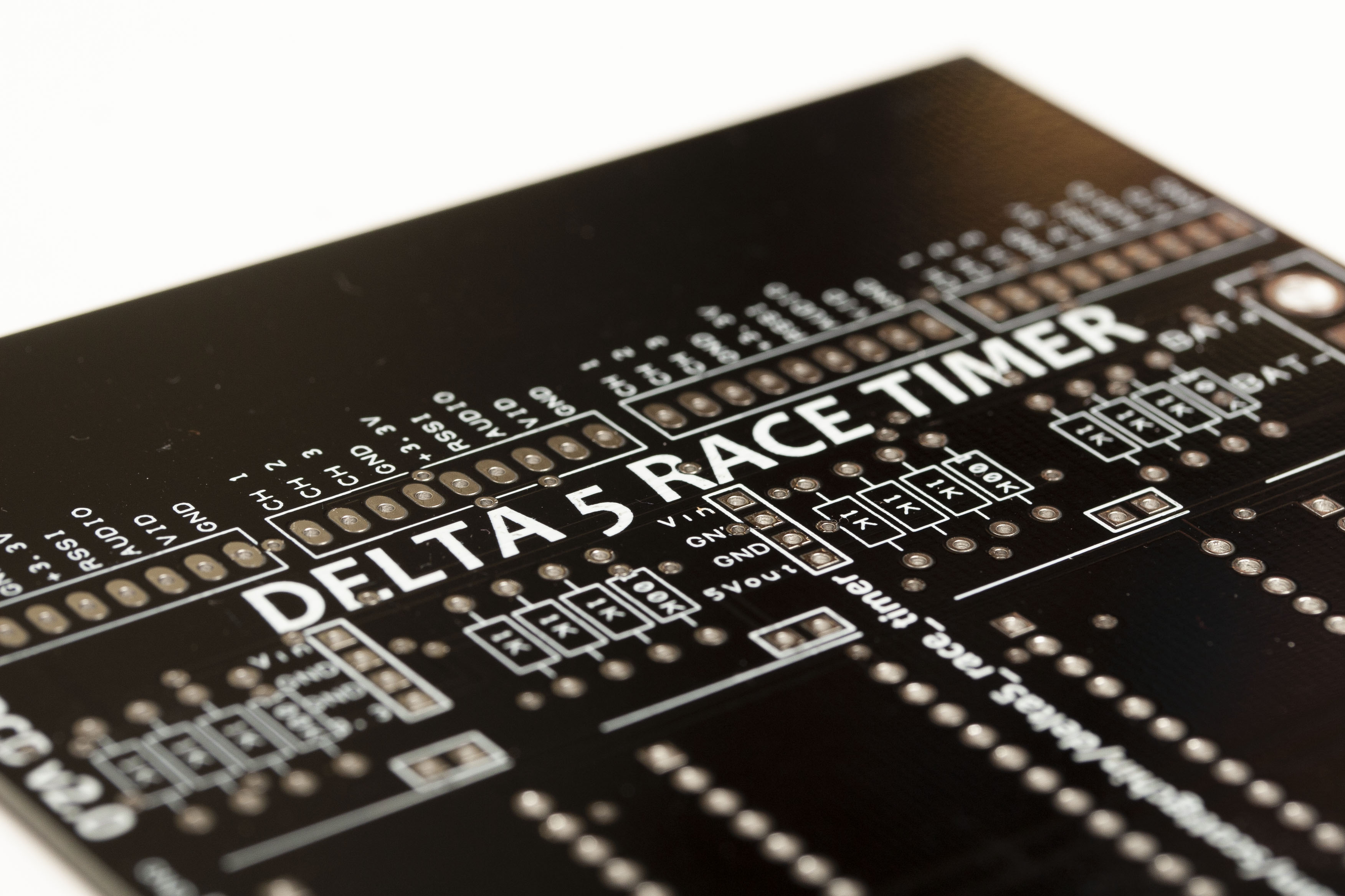
As you can see, each components location is labelled so the first thing we do is go ahead and start installing the components in the correct location. Start by installing the 1K and 100K resistors.
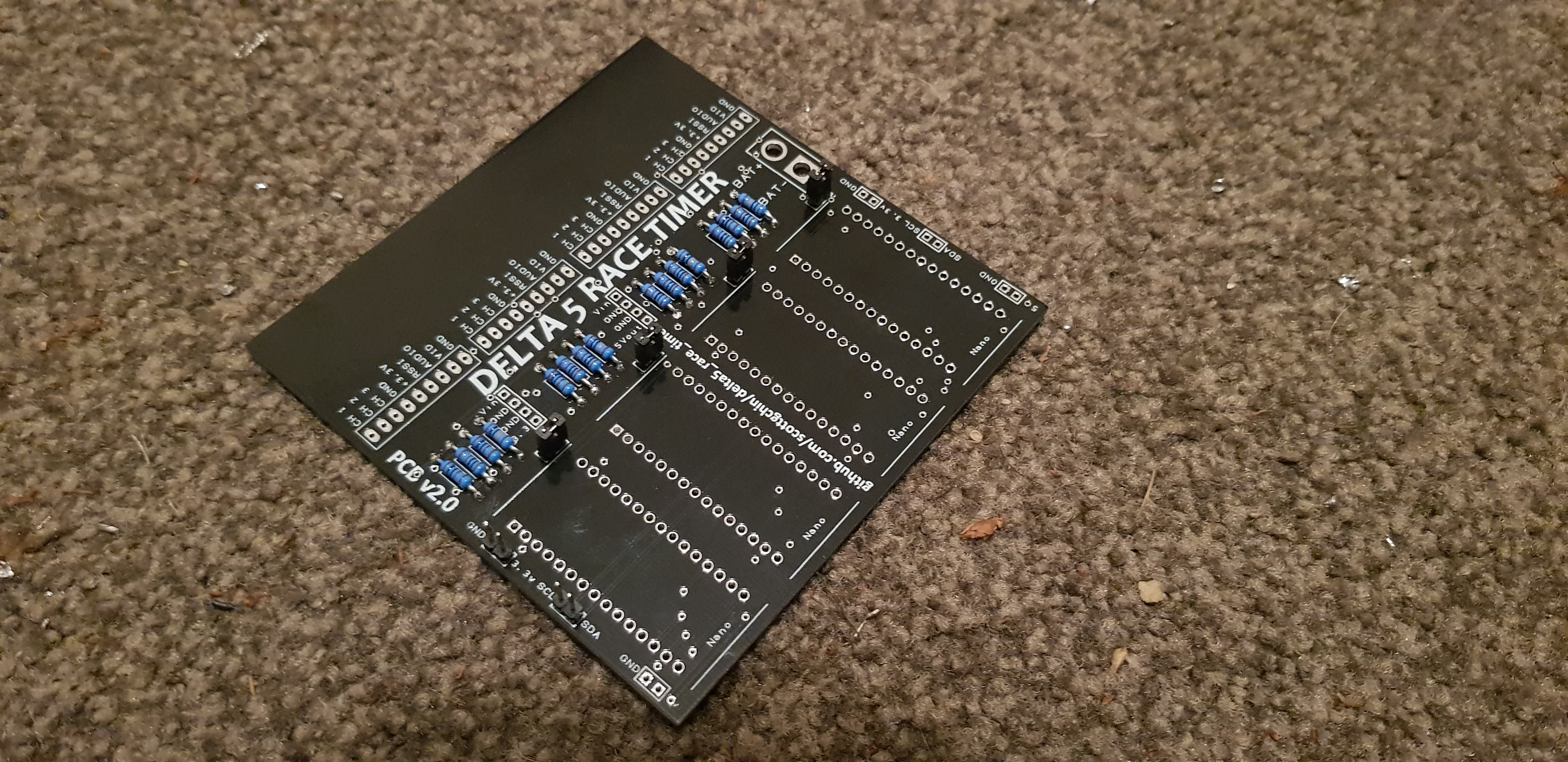
Next we will install the female pin headers for the arduino nanos and the voltage regulators.
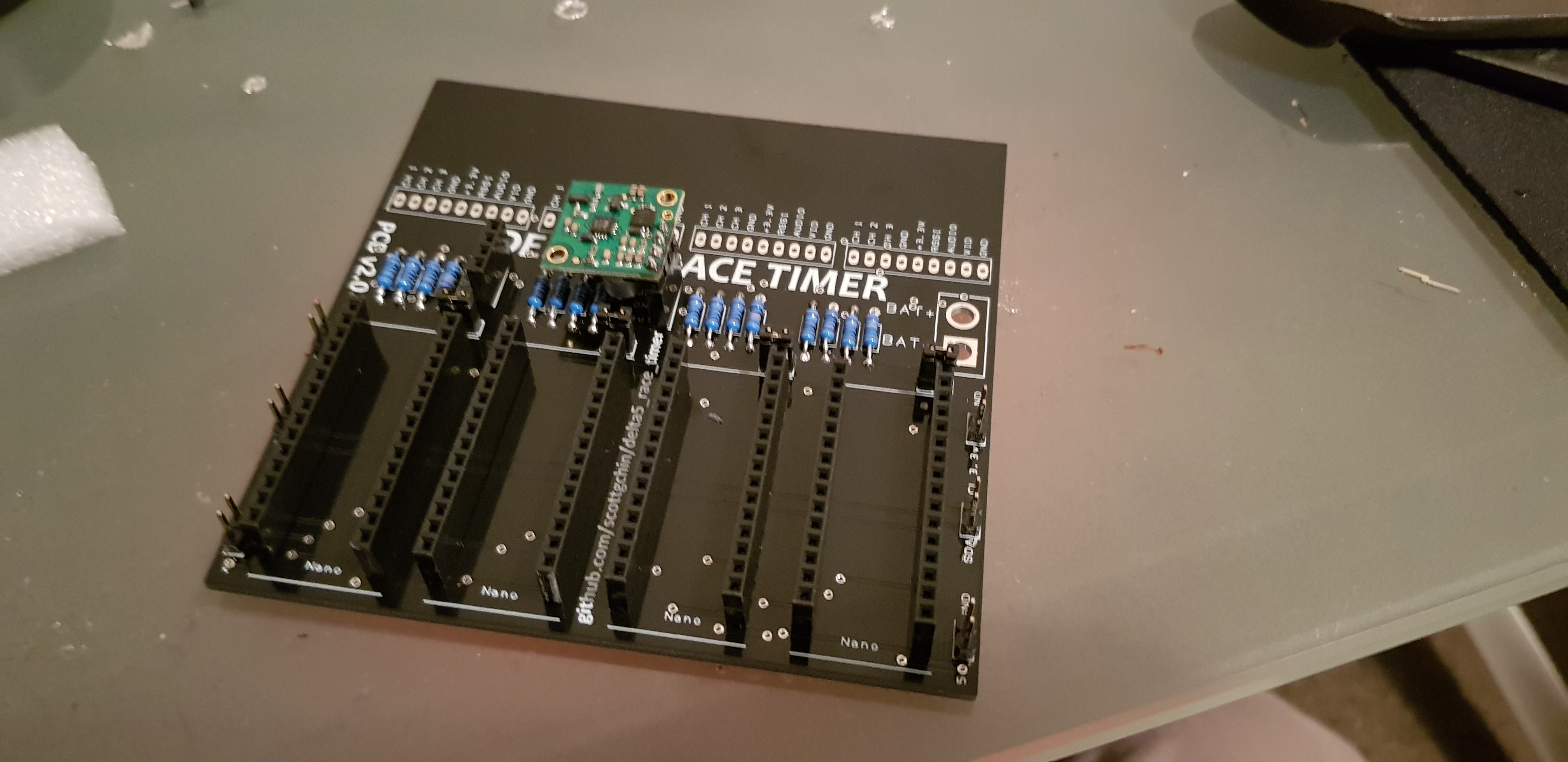
Now, we are ready to install the regulators and the arduino nanos. Make sure you get the plug in the regulators to the correct place, and also the arduino nanos in the correct way round! Using the female header pins allows hardware to easily be switched and replaced should it fail. Also install the 10 2pin header pins and apply jumpers to the pins above the arduino nanos. DO NOT apply jumpers to the 6 header pins on either side of the delta5 board. This will apply power to the arduino nanos. Some people also use female headers for the RX5808s and place a spacer underneath them for support should they fail, making replacement easy. In the example shown, I have soldered the RX5808s directly to the delta5 board.
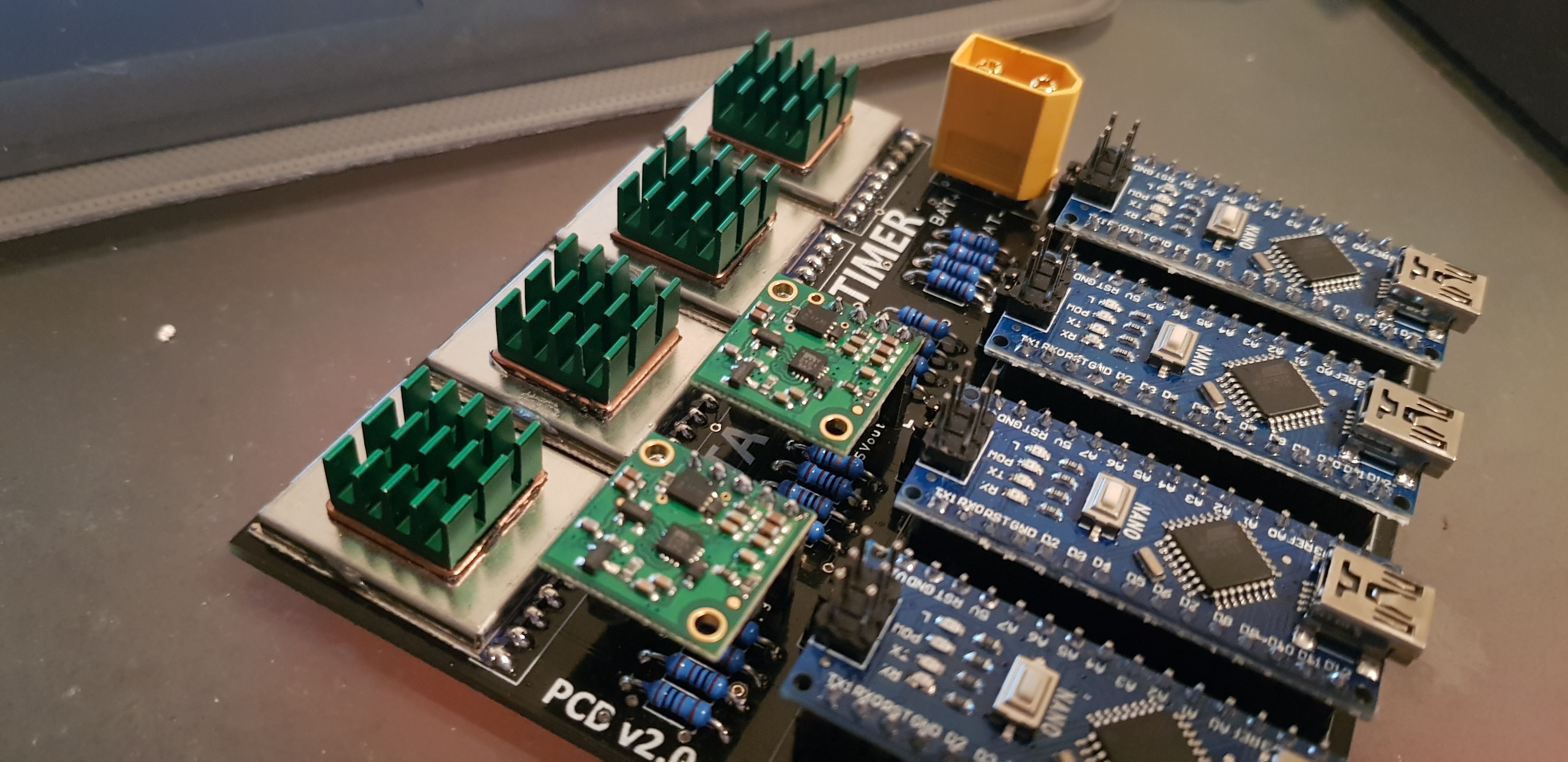
Now, we have the ardunio nanos, RX5808s, regulators and heat syncs installed. Now we are ready to install the raspberryPI and install the components into the enclosure.
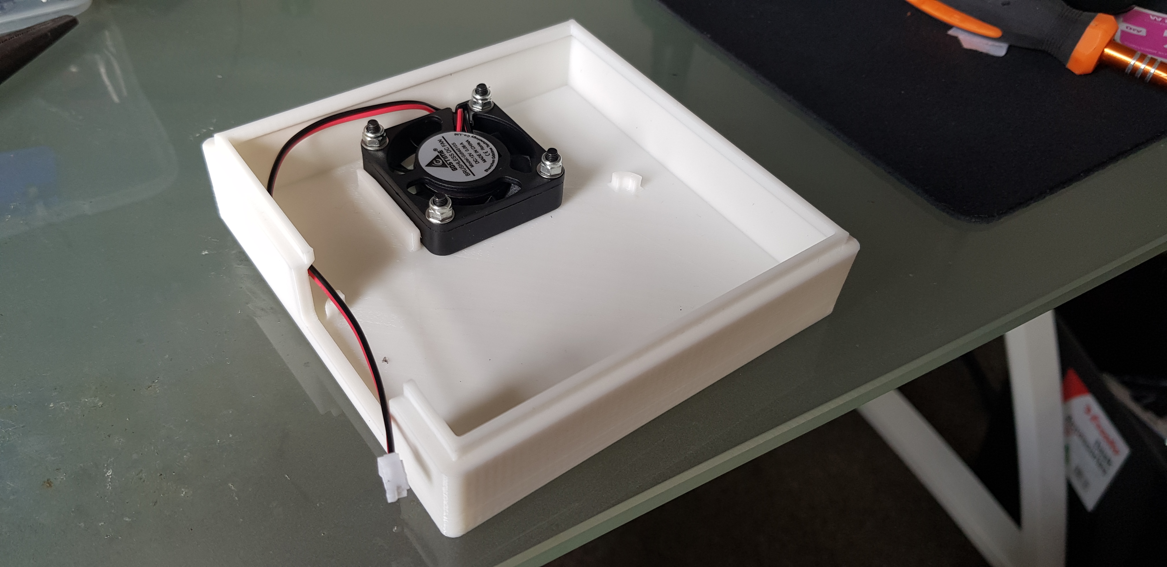
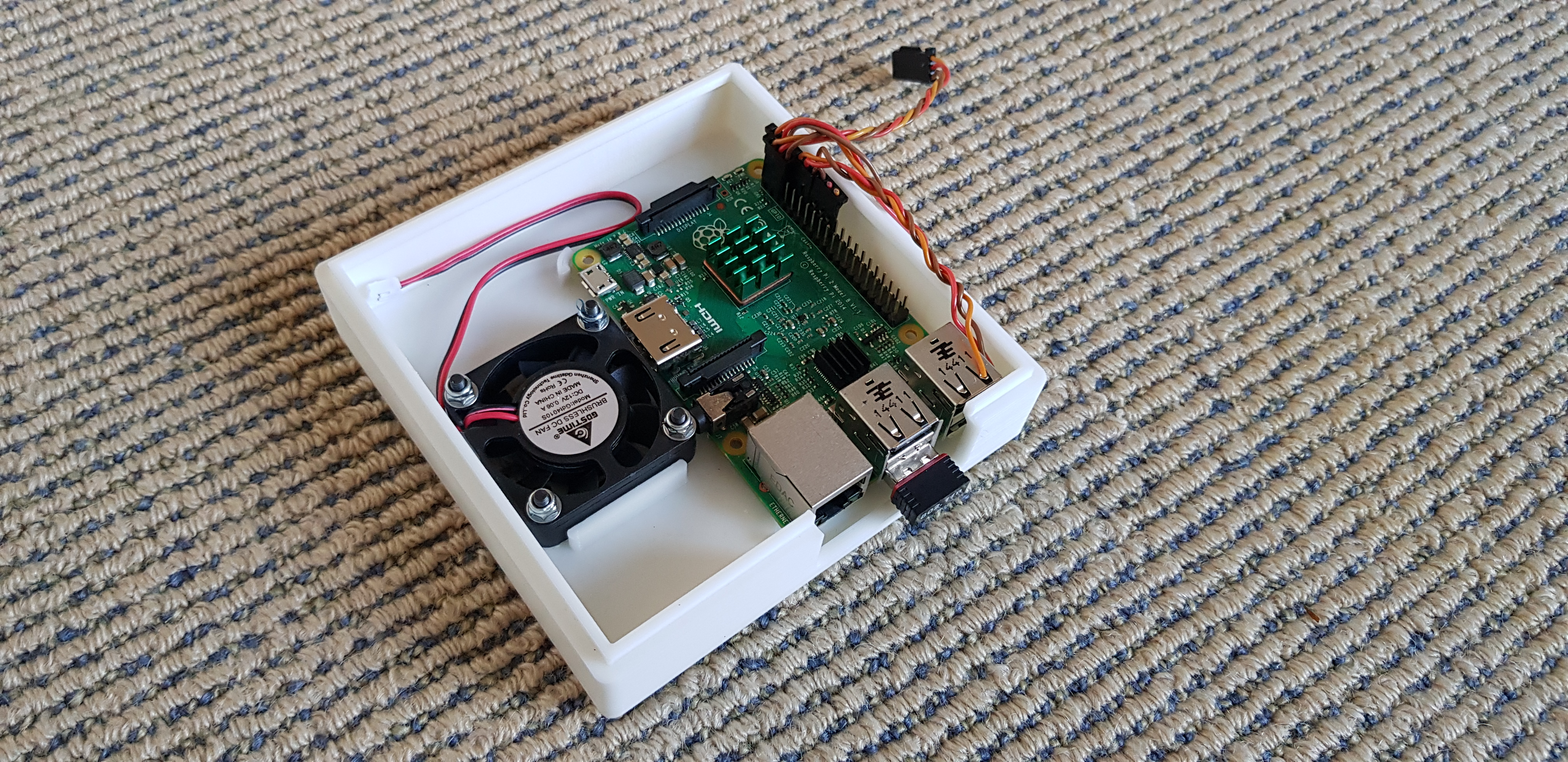
Lets begin by installing the 40x40mm fan! In my case the fan I had was a 12v fan so I was able to wire it straight to the battery supply. If your fan is 5v, just take 5v from the 5v regulator output to supply the fan with power.
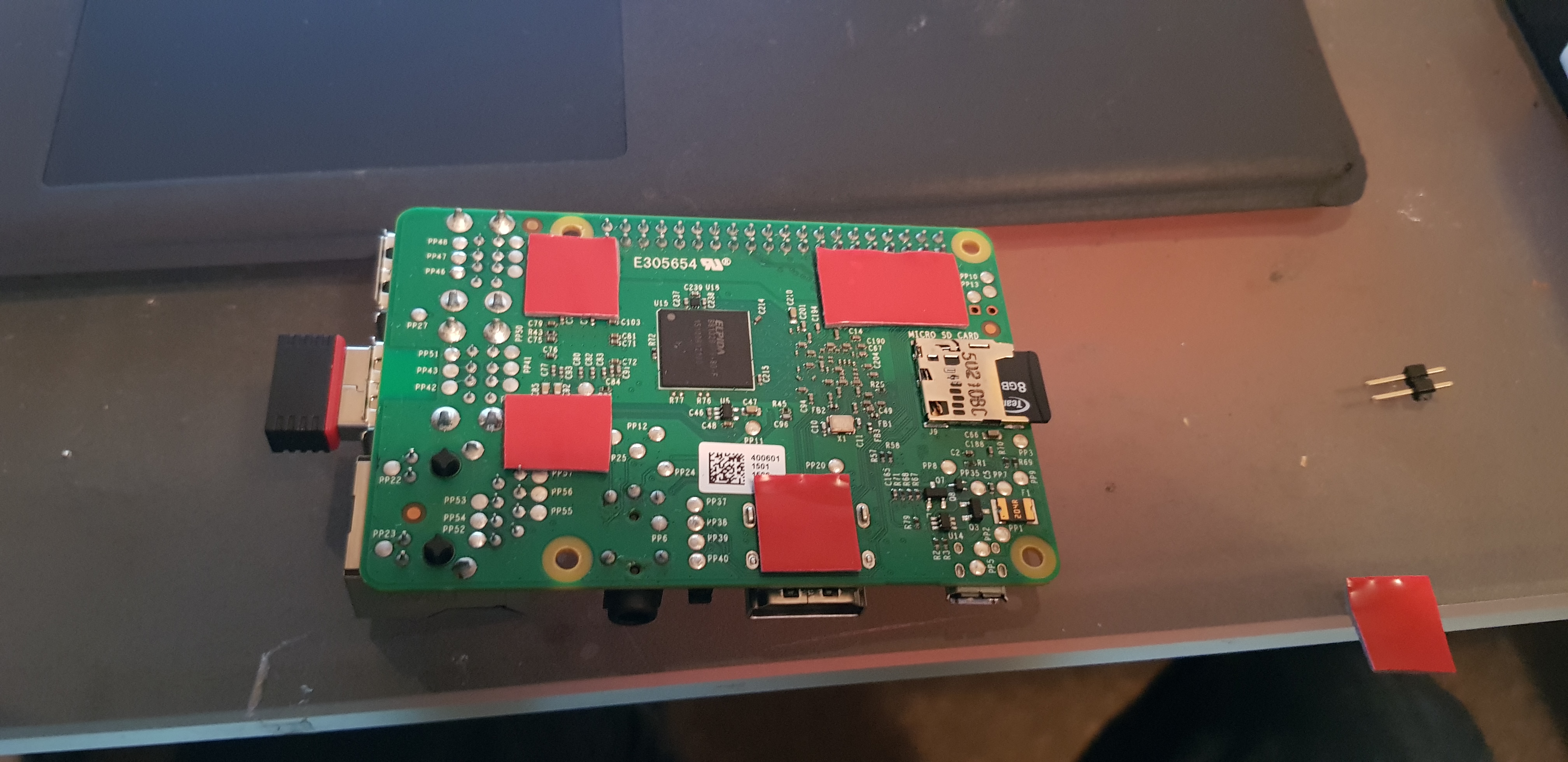
Now, we install the RaspberryPI alongside the fan! Using double sided tape to stick down the PI, it fits perfectly in this enclosure. Inserting and removing the SD card is a little tricky, but is possible. I used the same method to stick down the delta5 PCB to the other side of the enclosure.
Thats it for installing the hardware. Now we have both the delta5 board, all the RX modules, the regulators and the PI installed. Lastly wire up a XT60 or alternate power source to the board for power.
With that done, we are now ready to connect the PI header pins to the delta5 board. The delta5 communicates over I2C with the nanos, so we need to wire the nano to the PI I2C bus. This is done by connecting the header pins on the left and the right of the delta5 board. There are 3 sets of double headers on each side of the board, one side is for connection to the PI, the other is for adding an additional delta5 board if you choose to build a 8 node timer. These links are paralleled directly to the other board. If you are only building a 4 node timer as in this example, you will only need to use one side of these header pins! Below is a pinout of the RaspberryPI GPIO headers.
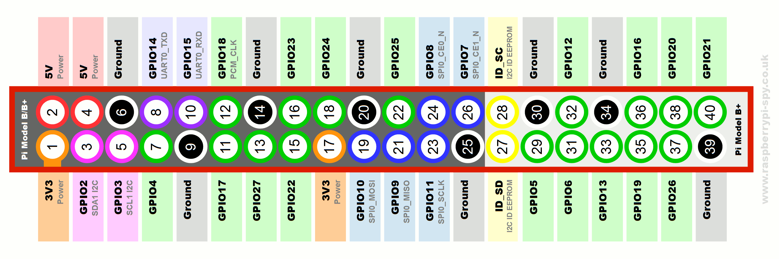
The pins we are interested are pins 4 and 6 and 3 and 5. Working from the delta5 board, we connect the GND to pin 6 and the 5v to pin 4. This supplies the RaspberryPI with 5v to power the PI.
Next we connect the I2C bus. Again, working from the delta5 board, connect the SCL to pin 5 (SCL on PI) and SDA to pin 3 (SDA on PI) and thats it. That is all the required connections between the delta5 board and the PI.
Before powering up I suggest you check the output voltages for the correct voltage to avoid doing any damage! If all goes well you should now have power on the arduino nanos, RX5808s and the RaspberryPI. Continue to page 2 for the software setup and Arduino programming.


All Comments
Awesome bro
Awesome article about the racetimer, but username and password dont work and the Admin login is also missing.
Could you please be so kind and share those information with us.
Hey man. The admin login for the web server didnt work? Should be admin and password as rotorhazard. Are you able to browse to the web server?
Yeah, that work. Thank man
Thank you for the guide and the pre-built image. Made it super quick to switch over from Delta5!
Great, glad it helped you. Stay tuned for new releases of RotorHazard, there are some cool upcoming features including split timing!
I flashed the 2.1.1 .img, but I don’t see the AP, how can I enable the AP to get the SSID to show up?
Thanks,
Hi Quy, the easiest way to do this is to plug in a second USB wifi dongle. You should then get your SSID show. If you do not have one, do the following after connecting your timer to your router via Ethernet. This is because the WiFi AP is assigned to WLAN1 but the default wifi interface built into the PI is on WLAN0. Here we need to reassign the AP and DHCP server to use WLAN0 instead of WLAN1.
1. run sudo mv wpa_supplicant-wlan0.conf wpa_supplicant-wlan1.conf
2. sudo nano /etc/dhcpcd.conf
Find the following line and replace wlan1 with wlan0
interface wlan1 – Replace with wlan0
static ip_address=192.168.10.1/24
static routers=192.168.10.1
static domain_name_servers=192.168.10.1 8.8.8.8
3. sudo nano /etc/dnsmasq.conf
replace interface=wlan1 with interface=wlan0 – Hit ctrl x and y to save.
4. sudo nano /etc/hostapd/hostapd.conf
replace interface=wlan1 with interface=wlan0 – Hit ctrl x and y to save.
5. sudo reboot
You should now see the ‘racetimer’ SSID broadcast.
Hi Dean,
So I got it figured out with some ‘googling” … LOL
So I reimaged the SD card again to be sure to start fresh and when I ssh to the PI, I noticed a message saying WLan0 was disabled by rfkill, so I entered the following command:
ifconfig – (I was not able to see the WLan0 interface)
I then did the commands:
sudo rfkill unblock 0
sudo reboot
once I made a ssh connection again, I tried:
ifconfig – (I was now able to see the WLan0 interface)
I went back through your instructions, but for the wpa_supplicant-wlan0.conf .. this was located in /etc/wpa_supplicant/ folder correct?
I’m now able to see the “racetimer” SSID
Thanks.
Hi Dean,
Thanks for the instructions, unfortunately it didn’t work for me or I may have missed something.
First off, I’m not a linux expert by any means, but when I do the “ifconfig” command I don’t see the Wlan0 interface. Is this why the commands you provided did not work?
I tried another image 2.0.1 and was able to get the Wlan0, so is the 2.1.1 img missing something?
Thanks.
Yes, you should be seeing a wlan0 or a wlan1 interface. If you don’t see any interfaces this would mean that your wlan interface is either faulty, or down. To bring the interface up you could try
sudo ifconfig wlan0 up
i figured it out in the comment above… thanks.
No worries. Glad you got it sorted.
When i download image 2.1.1 the .rar file does not open. It gives me a message saying this file is not an archive.
Nevermind, seems my rar software is corrupt.
Glad you got it sorted.
hey thanks for the hard work .im having a hard time trying to boot from the compiled image.
the normal raspberry buster works but lots of the commands come back as fails and the compiled sd card 2.1.1 dosent boot and show on putty at all. ive been at this all day and im at a loose end now . is there a problem with the stable img? should i be doing something different than the normal boot version.. please help man . cheers . Nick
Hi Nick! I’ve updated the image. Could you try downloading again and flashing the new image and see if the SSID is broadcast as “racetimer”. I have moved the wpa_supplicant to wpa_supplicant-wlan1.conf so if you need internet access, you either need to use Ethernet or insert a USB wifi dongle and edit the wpa_supplicant-wlan1.conf in /etc/wpa_supplicant to your wifi details.
Cheers
hey Dean
Awesome ill try that again and let you know.
i got the buster one to almnost complete after 10 hours the other day lol but now plugging it back in i get this looping constantly “Raspbian GNU/Linux 10 raspberrypi ttyS0” so ive just formatted sd and started again.
Sweet, if you’re having consistent boot issues its almost 99% of the time a bad SD card. Try a different SD card!
Its weird as the sd is fine for the buster image. its writing the image now .did you change it to the 2.1 beta image as that is what its downloading as now? cheers
hey dean its booted from sd card but its maybe something I did loading all the files on the buster img.but im getting this login loop constantly
▒▒▒▒▒▒▒▒▒▒▒▒▒▒▒▒▒▒▒▒▒▒▒▒▒▒▒▒▒▒▒▒▒▒▒▒▒▒▒▒▒▒▒▒▒▒▒ ▒▒▒ѥ▒▒Ɂlogin:
Raspbian GNU/Linux 10 racetimer ttyS0
god this is not my forte lol .
Yup, boot loops and hangs are generally SD cards! Especially if its a fresh install.
ok ill try another one. its showing in my wifi though as racetimer so something is working . thanks man
[ 16.256020] i2c /dev entries driver
racetimer login:
Raspbian GNU/Linux 10 racetimer ttyS0
▒▒▒▒▒▒▒▒▒▒▒▒▒▒▒▒▒▒▒▒▒▒▒▒▒▒▒▒▒▒▒▒▒▒▒▒▒▒▒▒▒▒▒▒▒▒▒▒▒▒ѥ▒▒Ɂlogin:
Raspbian GNU/Linux 10 racetimer ttyS0
▒▒▒▒▒▒▒▒▒▒▒▒▒▒▒▒▒▒▒▒▒▒▒▒▒▒▒▒▒▒▒▒▒▒▒▒▒▒▒▒▒▒▒▒▒▒▒▒▒▒ѥ▒▒Ɂlogin:
Raspbian GNU/Linux 10 racetimer ttyS0
▒▒▒▒▒▒▒▒▒▒▒▒▒▒▒▒▒▒▒▒▒▒▒▒▒▒▒▒▒▒▒▒▒▒▒▒▒▒▒▒▒▒▒▒▒▒▒▒▒▒▒ѥ▒▒Ɂlogin:
Raspbian GNU/Linux 10 racetimer ttyS0
▒▒▒▒▒▒▒▒▒▒▒▒▒▒▒▒▒▒▒▒▒▒▒▒▒▒▒▒▒▒▒▒▒▒▒▒▒▒▒▒▒▒▒▒▒▒▒@▒▒▒ѥ▒▒Ɂlogin:
Raspbian GNU/Linux 10 racetimer ttyS0
▒▒▒▒▒▒▒▒▒▒▒▒▒▒▒▒▒▒▒▒▒▒▒▒▒▒▒▒▒▒▒▒▒▒▒▒▒▒▒▒▒▒▒▒▒▒▒▒▒▒▒ѥ▒▒Ɂlogin:
Raspbian GNU/Linux 10 racetimer ttyS0
4-fs error (device mmcblk0p2): ext4_lookup:1590: inode #21315: comm systemd: ige t: bad extra_isize 65535 (inode size 256)
[ 179.958102] EXT4-fs error (device mmcblk0p2): ext4_lookup:1590: inode #2065: comm rs:main Q:Reg: iget: bad extra_isize 65535 (inode size 256)
[ 179.988175] EXT4-fs error (device mmcblk0p2): ext4_lookup:1590: inode #21315: comm systemd: iget: bad extra_isize 65535 (inode size 256)
Raspbian GNU/Linux 10 racetimer ttyS0
▒▒▒▒▒▒▒▒▒▒▒▒▒▒▒▒▒▒▒▒▒▒▒▒▒▒▒▒▒▒▒▒▒▒▒▒▒▒▒▒▒▒▒▒▒▒▒▒▒▒▒ѥ▒▒Ɂlogin:
Raspbian GNU/Linux 10 racetimer ttyS0
▒▒▒▒▒▒▒▒▒▒▒▒▒▒▒▒▒▒▒▒▒▒▒▒▒▒▒▒▒▒▒▒▒▒▒▒▒▒▒▒▒▒▒▒▒▒▒▒▒▒▒ѥ▒▒Ɂlogin:
Raspbian GNU/Linux 10 racetimer ttyS0
so ive tried another sd card and the same happens .with the additional error lines now and then.
I haven’t got any nodes connected as I haven’t finished the build yet but im sure that’s not the problem .thanks for any help you can give me .
Very weird. How are you powering your pi? What is the current output?
its off the usb from pc .all working ok now im just triyng to update everything manually to the latest version from the 2.0.1 bad wifi connection is not fun with all this though :{
Cool. Yea I would recommend Ethernet
Hi Dean hope your’e well man ..Everything is working great with this timer ive got the external antenna installed and can connect over Ethernet too if i need to but im really struggling getting a wifi dongle working! Ive purchased one that is regocnised and is showing in ifconfig in wlan1 and i think the firmware is loaded ok but its the registering it on my network im having trouble with.. in the /etc/wpa_supplicant/wpa_supplicant.conf folder its empty and if i add credentials in there nothing happens .aloso same with /etc/wpa_supplicant/wpa_supplicant-wlan1.conf folder. I added stuff to the interfaces folder but then my ssh stopped working and i had to dig out the usb serial one again lol ..please help brother ,your’e much better at this than me .. cheers
Hi Nick
Can you post your WPA supplicant.
Also, is the wifi dongle acting as a client? And if so make sure the network you are connecting to is offering DHCP.
Thanks Dean, haven’t had chance to look recently but I had an idea to connect to my android phone via USB.. I cannot connect to it via ethernet as my phone doesn’t seem to pick it up using a ethernet to USB dongle. So I’ve managed to get the command line to connect to the broadcast ip using a USB cable and would like to know if I could adjust the broadcast of race timer to run out through the ip of the USB? Is this possible? Would be so much easier that way and I could get a 10m cable and have solid connection just unsung my phone.. Thanks for any help dude
Can you elaborate a little more. Are you trying to use an external AP connected via Ethernet?
Hi thanks for the guide! I used the image provided for 2.1.1 on a pi 3B+
The AP seems to be running out of the box, but the dnsmasq service fails to start.
The AP shows up and I can connect, but it just sits there “obtaining Ip address” and does nothing.
Any ideas? Reflash?
Also, just noticed the link to the 2.1.1 file is the same as the 2.1.0 beta 1…
Is there a link to the 2.1.1 image?
Many thanks!
Hey Jaemie.
Sorry the link is
https://mega.nz/file/77oSCAQa#dS9icw8gu9WxiH7Vo4kAIgMjwX1FcsmbRaCOHXX1iL0
Cheers.
Thanks Dean!
Pending this flash I have some RSSI issues. Is there a way I can chat or talk this issue through? I’m happy to pay for the help!
I’m in Australia if timezones are an issue.
You can throw your adapter on a static address on the 192.168.10.0/24 network.
Set a static IP on the adapter and your computer.
IP: 192.168.10.100
Mask: 255.255.255.0
No gateway or DNS
Try connect again and you should be able to ping or SSH 192.168.10.1.
Now you can check the issue with DNSMasq once connected.
I’m getting this error now…
● hostapd.service – Advanced IEEE 802.11 AP and IEEE 802.1X/WPA/WPA2/EAP Authenticator
Loaded: loaded (/lib/systemd/system/hostapd.service; enabled; vendor preset: enabled)
Active: activating (auto-restart) (Result: exit-code) since Mon 2020-05-25 06:32:14 BST; 879ms ago
Process: 774 ExecStart=/usr/sbin/hostapd -B -P /run/hostapd.pid -B $DAEMON_OPTS ${DAEMON_CONF} (code=exited, status=1/FAILURE)
why attached a wifi antenna before powering? without this mod there is also a open circruit and we powering it up where is the diffrent?
Sorry I dont understand your question. Cheers
When I start a race the laps aren’t being recorded. Sensor tuning seems good. Any ideas?
Make sure you are getting RSSI readouts on the tuning graph. Also make sure the peaks go above your enter at RSSI.